![]()
Driver Technology for Variable Speed Applications
In an industry that is continuously pushing for higher system efficiency requirements, there is continuous innovation in technology. The use of variable speed drivers and the advancing technology are key to improving the efficiency of the system. Driver technology has improved and developed quickly to respond to this requirement. It is important to understand variable speed driver technologies used within the pumping industry. Defining the terminology of these technologies along with each type of driver, its basic function, and limitations is important for the industry to understand and increase the adoption of new technology for a more efficient pumping system.
The induction motor powered by a variable frequency drive is the standard drive system used within the pump industry to operate at variable speed. Other technologies have been developed, each of which has benefits and drawbacks that are being discussed. Leveraging these technologies within the applications leads to much higher system efficiencies over the operating range. Regulations from governing bodies continue to evolve through increased scope and overall system efficiency requirements. It is important to understand what testing standards are available for power drive systems and how they fit within current and future efficiency regulations.
Variable Speed Overview
Variable speed operation has become a key function in today’s pumping systems. Varying the speed of a pump allows it to adapt to the system’s demand and can impact the overall energy consumption. In a fixed-speed pumping system, no matter what output is needed, the motor and the pump only spin at one speed outputting the same amount of fluid and consuming the same amount of energy. Any demand reduction can only be achieved by throttling the pump, wasting this excess energy. Varying the speed of the pump allows the pump to only deliver the head and flow that is required by the system. In electric motors, when you change speed, the efficiency drops. However, this efficiency drop is offset by the lower power level required and still allows for more energy-efficient system operation. In this article, we will review alternate motor designs for use in variable speed. There are benefits and constraints to each.
Induction vs Synchronous Motors
Electric motors (when used as pump drivers) are responsible for providing the rotational speed and torque required by the pump shaft. This is achieved by converting electrical energy into mechanical energy through the interaction of magnetic fields and electrical current. The rotational motion generated by the motor drives pumping components such as an impeller, a piston, a plunger, a gear, or a screw.
Components of an Electric Motor
There are key components that make up an electric motor, each contributing to its operation and efficiency. These components include the rotor, stator, shaft, bearings, and motor casing (or housing), which are crucial for transferring mechanical energy, supporting the rotor, and protecting internal components from the external environment.
Induction Motor Basics
The following applies to the common three-phase, asynchronous induction motor design.
The stator acts as the stationary part of the electric motor that surrounds the rotor. It contains stacked layers of steel laminations that include slots for the electrical windings which carry the alternating electrical current. Electrical connections to the stator windings are brought out to a terminal or conduit box. The connection is made to an electrical power source to pass current through the stator windings. A current traveling through a loop of wire creates a rotating magnetic field (RMF) along the axis of this loop. The plots seen in Figure 1 illustrate current over time and show how the maximum current is passed from Phase A to Phase B to Phase C in a three-phase motor.
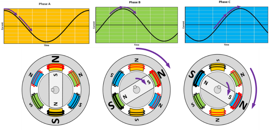
Figure 1: Illustration of how a loop creates a magnetic field
The symmetry of a three-phase electrical current provides an inherent rotation of the internal magnetic field. The stator’s role is crucial as it provides the electromagnetic reaction for the motor’s operation.
The rotor is the physically rotating part of the electric motor. It consists of a stacked set of ferrous laminations mounted on a shaft. The laminations have slots to hold the electric conductor bars (rotor bars). The rotor bars act as a closed conductor, short-circuited at each end by end-rings. This type of rotor is often referred to as the squirrel cage. There are no electrical connections to the rotor. The stator’s rotating magnetic field induces an electromotive force (EMF) on the squirrel cage rotor bars. The EMF then produces current in the rotor bars, thus giving a current-carrying loop situated within the rotating magnetic field. An electromagnetic force will be produced on the current-carrying rotor bars and the rotor will start to rotate. In an induction motor, it will always rotate at a speed slightly less than the speed of the rotating magnetic field. This is called “slip”. When a load is applied to the shaft, the motor will produce torque to maintain its rotational speed. All energy transfer is accomplished by electromagnetic induction.
To summarize, the induction motor’s essential character is that torque is a result of induction and slip.
Synchronous Motor Details
Synchronous motors operate at the running speed of the frequency of the applied voltage. As a result, synchronous motors do not experience slip. There must be some excitation to start though, as the speed difference between the stationary rotor and the RMF in the stator will not allow their poles to lock on start-up. This is accomplished in different ways and, as a result, synchronous motors have been split into non-excited synchronous motors and current-excited synchronous motors.
- Non-excited synchronous motors: Non-excited synchronous motors use ferromagnetic materials in the rotors to interact with the stator. The major design types will use magnets integrated into the rotor or the principle of reluctance, discussed later in this article.
- Current-excited synchronous motors: Current-excited (also referred to as separately excited) synchronous motors are fitted with a wound exciter on the rotor to provide the rotor field required to generate torque. The exciter on the rotor is similar to the operation of an induction motor rotor. This is more common for larger horsepower motor applications.
You must evaluate the complete system to determine if an induction or synchronous motor is the best choice for the application. In a synchronous motor, there is no induced current in the rotor. The lack of induced current eliminates the induction losses and results in increased efficiency, higher power density, and lower heat generation. However, the system requires a variable frequency drive (VFD).
A life cycle cost analysis should be done to evaluate if the reduction of energy costs can justify offsetting the increased cost of the motor and drive system. The softer benefits of a reduced footprint and reduced weight may also be a consideration.
This paper focuses on non-excited synchronous motors. In the following sections, we will cover the benefits of these synchronous motor topologies.
Benefits of Synchronous Motor Technologies
There are common benefits for synchronous motors versus an induction motor. This section explores the top considerations.
Efficiency Performance
When motors run at a single speed, the efficiency across the entire speed range is not important. There is a significant reduction in energy consumption by adjusting the operating speed to meet the demand of the application.
This is where synchronous-based designs experience their largest efficiency benefit. In an induction motor rotor run at low speed, there is a higher proportion of total energy loss than in the synchronous motor rotors. Lower energy loss across a wide speed range means that a synchronous motor has a higher efficiency not just at the rated motor speed, but across the entire speed range. As a result, synchronous motor efficiency curves are “flatter” than induction motor efficiency curves which can be seen in Figure 2. This is commonly referred to as the “flatness” of the efficiency curve. This ‘flatness’ results in efficiency gains when the motor speed is adjusted to meet demand. Considering it’s common to spend as much as 75% of the operating time below full speed the impact of reduced energy consumption is significant.
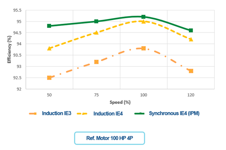
Figure 2: Efficiency Curve of Synchronous Motor and Induction Motor
Additionally, the U.S. Department of Energy (DOE) performed a study with Berkeley Labs which concluded that adoption of advanced technologies, installation of VFDs, and pump impeller trimming are the greatest sources of energy, CO2, and cost savings. These measures are associated with matching the actual motor speed to the demand of the system, indicating that synchronous motors provide increased energy savings.
Thermal Performance
In induction motors, the induced currents will have losses that result in additional heat in the rotor. Removing these losses in synchronous motors is the primary source of efficiency gain. The reduced rotor temperature also has a maintenance and reliability benefit. Reducing the rotor temperature results in less heat transfer to the bearings. Keep in mind it only takes a decrease of 10°C (50°F) to double the grease life. Operating at a lower internal temperature can be expected to reduce lifecycle costs by improving the lifetime of the electrical components of the motor.
With less heat to dissipate, the synchronous motor could be designed using less material for the same output, resulting in lighter weights and the ability to reduce the footprint. This offers the ability to achieve much higher efficiency, up to IE4 and IE5, as defined above.
Technology Comparisons of Synchronous and Induction Motors
The following sections will describe the basics of five synchronous motor designs. Figure 3 below compares a standard squirrel cage induction rotor to the five synchronous motor designs. They are organized by their different physical rotor construction.
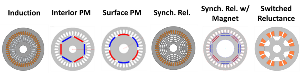
Figure 3: Cross Section of Technologies Used in Synchronous Motors
Magnets
First some comments on the use of permanent magnets in synchronous motors.
Rare earth magnets (REMs) have the highest magnetic energy density to maximize torque density and efficiency levels. However, a restrictive global supply chain enhanced by increased electric vehicle demand and sensitivity to demagnetization at elevated temperatures poses issues to manufacturing and service.
Today there are more synchronous motor designs utilizing lower-strength magnets (such as Ferrite). Lower-strength magnets are easier to handle in production and service in the field. The materials that make up these magnets reduce some of the supply chain challenges.
Interior Permanent Magnet
An internal permanent magnet AC motor (PMAC) has magnets embedded into the rotor. The natural magnetic flux generated in the permanent magnets produces alignment torque. As the magnet’s magnetic field wants to align with the rotating magnetic field from the stator it results in the rotational output and torque.
PMACs must be started and controlled by VFD. The only way to alter their speed and torque is by changing the stator AC frequency. PMACs are not self-starting. There is the possibility of adding a squirrel cage into the design only for starting as an across-the-line start PM motor.
Interior permanent magnet design allows for better mechanical retention of the magnets.
Surface Mount Permanent Magnet
Another version of PMAC has magnets bonded to the exterior surface of the rotor. This design:
- Has lower mechanical strength (depending on the bond of the magnet to the rotor) and a limited high-speed capability.
- Operates purely with magnet alignment torque.
- Does not take advantage of reluctance torque.
- Lower inductance but can vary speed easily.
- May use REMs or other magnetic materials.
It is important to consider the impact of the alignment of magnetic field lines of the rotor. In an internal magnet rotor, the magnets are also positioned to align with stator magnetic field lines. If they are mismatched, the reluctance, which is the magnetic equivalent to electrical resistance, results from the longer path through the rotor. Surface mount permanent magnets do not benefit from this increased reluctance that results from misalignment. However, due to the proximity of the magnets to the stator, internally mounted magnets can get extra torque.
Synchronous Reluctance Motor
Synchronous reluctance motors (SynRM) do not use magnets to generate a magnetic field in the rotor. Instead, the rotor designs exploit the concept of magnetic reluctance to generate torque. In short, the concept of magnetic reluctance looks for low reluctance conditions where maximum energy is stored in a magnetic field.
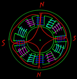
Figure 4: Displaying Slots in Stator and Flux Lines Only
The SynRM rotor is designed with open slots to facilitate the creation of this low reluctance position. In the low reluctance position, the magnetic flux lines take the shortest route between poles.
The rotor, due to magnetic reluctance theory, will be attracted to this low reluctance position in relation to the stator’s magnetic field. Torque will be produced by the rotor to stay in the low reluctance position of the continuously rotating magnetic field from the stator. The rotor in a low reluctance position within the stator’s rotating magnetic field is represented in Figure 5 below.
Figure 5: Showing Stator, SynRM Rotor, and Flux Lines
The SynRM motor design is a very simple, rugged design, but generally demands more input current to the VFD due to lower power factors.
The addition of a die-cast aluminum rotor also allows for volts/hz VFD operation. Otherwise, like PMAC, it must be started and controlled by a vector VFD.
Synchronous Reluctance with Internal Magnet
It is possible to augment the synchronous reluctance rotor by adding magnets within the rotor slots. This creates a magnet-assisted version of the synchronous reluctance motor. The share of reluctance torque is significantly more than the internal PM motor as additional torque is generated by this increased reluctance. This permits the use of lower-strength magnets (ferrite or similar) to assist the rotor’s magnetic field strength which offers improvements in power factor and reduces the current required from the VFD.
Switched Reluctance
The oldest technology to be described in this paper, the switched reluctance motor, has a simple physical design compared to those described previously. This technology requires special software within a VFD to operate. It is a type of stepper motor with an inverted winding setup.
An electronic control system, which is triggered by a position sensor, is used to switch the stator poles on and off. This will require a compatible VFD selection for switched reluctance motors. It is the one design that will not use a Vector or Volt per Hz VFD. As such this topology is the least common.
Considerations for VFDs with Synchronous Motors
The two main types of VFDs currently used in the pumping industry are scalar (volts per hertz) and vector control drives (optimizes the torque);
- Scalar drives are the simplest form of VFD for control of a motor. The VFD outputs a basic volts per hertz ratio. In most cases, the VFD is capable of being programmed to adjust the ramp rate or slope of the volts per hertz ratio but does not adjust based on operating conditions.
- A vector control VFD attempts to build a motor map either by programming in motor data or by doing a sensing process of the motor to determine those characteristics. Those characteristics normally include the motor power factor and equivalent circuit data. With the incremental motor data, and the ability to monitor operating characteristics, the VFD makes output adjustments to the motor to maintain performance.
It is important to understand which type of VFD is required to power different types of motors. A standard induction motor can utilize a scalar VFD to become a variable speed mechanical output device. When working with synchronous motors the VFD selection requires additional consideration. A synchronous motor has no slip. This requires most of them to only be capable of operating using a vector control type of drive. There is a unique synchronous rotor design that adds aluminum rotor bars similar to an induction motor to allow across-the-line start. This specially designed rotor can operate like an induction motor on a scalar type VFD. This is a significant advantage that allows for higher efficiency performance of the synchronous motors but requires a vector capable drive.
Synchronous and Induction Variable Speed in Pumping Systems
Any type of variable speed motor offers energy savings if programmed for the system correctly. However, synchronous motors and induction motors offer different benefits. The decision, as in most cases, comes mostly down to cost.
A few things should be considered when selecting a variable speed motor option to operate a pump.
- Motor/Drive Cost
- Life Cycle Cost, Energy Consumption
- Additional Considerations:
- Installation
- Operating Range
- Audible Noise
Motor and Drive Cost Considerations
An induction motor, not having permanent magnets or requiring a closed loop capable drive, offers a lower initial cost option to operate a motor at variable speed. The induction motor is limited in the top-end efficiency levels it can hit. A synchronous motor may cost more initially but has longer-term benefits.
Life Cycle Cost and Energy Consumption
Synchronous motors can achieve higher peak efficiency than induction. They also maintain a higher efficiency over a wider speed range, defined as a flatter efficiency curve. The life cycle cost of the system yields more savings. Overall, the system requirements for input and output of a variable speed system are the same for either an induction or synchronous motor. The power range for synchronous machines, as well as the initial cost, may be a barrier. It may be difficult and cost-prohibitive for standard induction motors to exceed NEMA Premium efficiency levels (IE3). Synchronous technology may be the most suitable option to achieve higher IE4 or IE5 efficiency levels for smaller power ratings [less than 75 kilowatts (kW)].
The design and operation of pumping systems are focused on energy consumption, driven not only by end users desiring to reduce operating costs but also by increasing government regulations. Variable speed drive systems including both induction and synchronous motors are key drivers in improving energy conservation.
Additional Considerations
Variable-speed drivers have both advantages and disadvantages, which should be evaluated for each specific pumping application. Variable-speed drivers can add to the complexity of the system and may dictate that a thorough analysis of the pump/driver assembly be performed. A review should be made with the pump and motor manufacturer before the final selection.
Information on other important considerations for variable speed pumping systems can be found in the resources linked at the end of this article.
Upcoming Regulatory Changes for Synchronous Motors
Currently, synchronous motor drive systems are outside of the DOE’s test and regulatory scope. Testing of an induction motor is fairly straightforward but testing synchronous motors is unique.
The DOE is developing test standards for synchronous motor technology alongside NEMA and IEC. At the time of this article, the DOE does not recognize a calculation-based for a PEI value for synchronous motor and drive. To take advantage of the improved PEI values that a synchronous motor and drive can achieve, a full wire-to-water test is required for the pump to the DOE system curve. HI is currently partnering with the DOE to create coefficients to demonstrate the difference between synchronous and induction motors.
Testing of synchronous motors is unique because many of the global testing standards do not apply specifically to synchronous designs. The testing standard IEC 60034-2-3 does include testing methods for synchronous motors. The standard details a process to test the motor and the VFD to allow separation of the losses between the motor and the VFD. The standard has testing points beyond the full load point to allow for comparison of the motor at part load and speed. The process in IEC 60034-2-3 is also a key component in the total power drive system (PDS, Motor +VFD) efficiency testing process as outlined in IEC 61800-9-2. The EU and the United States DOE are using these standards for evaluating system efficiency for the PDS of both induction and synchronous design motors.
Conclusion
The pump industry is in the middle of a huge technology shift. This shift started when VFDs became more widely and economically available. The VFDs allowed the industry to use only the power needed. Now as this technology wave continues, the wide adoption of variable speed pumping has happened and we have moved into the next phase of technological advancement. One of the key components of that next phase is the electric motor. With the push for lower energy consumption, higher-efficiency motor technology is advancing. It is important to understand how these different motor technologies operate and the special designs that each application requires. These motors will benefit pumping systems as a whole and will be the future of pumping efficiency.
Additional Resources
Below are key resources to help you understand in greater detail variable speed pumping operations.
- ANSI/HI 9.6.4 Rotodynamic Pumps for Vibration Measurements and Allowable Values (2022)
- ANSI/HI 9.6.8-Rotodynamic Pumps – Guideline for Dynamics of Pumping Machinery (R2021)
- Application Guideline for Variable Speed Pumping (2017)
- DOE Berkley National Laboratory Study
- Drivers Application Guidebook: Electric Motors (2019)
- Pump Life Cycle Cost: A Guide to LCC Analysis for Pumping Systems – 2nd Edition (2021)
- Pump System Optimization: A Guide for Improved Energy Efficiency, Reliability, and Profitability (2018)
- Variable Frequency Drives: Guidelines for Application, Installation and Troubleshooting (2014)
SUBSCRIBE TODAY
Get the latest pump industry news, insights, and analysis delivered to your inbox.